Saturable Reactor Winding Configurations
Osborne has been involved in a wide variety of saturable reactor design projects over the years. Magnetic amplifier technology involves unique techniques that can be tailored to match the fit, form, and function of your application. We’ve prepared the illustrations below to share six established saturable reactor element core and coil configurations.
Note: the illustrations below are inspired by William Geyger and his influential book “Magnetic Amplifier Circuits”.
Arrangement A: Dual Ring Cores
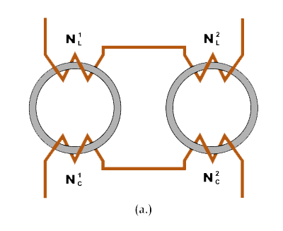
The dual ring core approach uses toroidal cores. These cores have an advantage of inherently small air gaps in the flux pathway. They offer relatively high permeability and relatively high inductance and reactance. This saturable reactor winding approach can be limited in higher power applications due to turns insulation constraints.
Arrangement B: Dual EI Cores
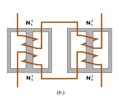
The dual EI core approach uses grain oriented silicon steel or nickel iron alloy lamination form core material. The cores are deployed in tandem and wound in series. Air gap effect needs to be taken into account. Advantages to this approach include relatively higher power handling capacity and thermal management in extreme operating environments.
Arrangement C: Single EI Core

This is the most common saturable reactor element configuration. AC coils are wound on the two outside legs and the DC control winding is wound on the center leg. This approach has a distinct disadvantage of disturbing hysteresis effects due to the absence of AC flux in the core’s center leg. When form factor demands this approach, Osborne recommends the split center leg core approach.
Arrangement D: Split Center Leg Core
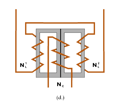
The form factor of this approach is nearly identical to the single EI core approach, with one major difference: the center leg of the core is split. This approach commonly uses C cores. The AC coils are wired together in a manner that mitigates AC flux flow in the center leg – the AC fluxes sum to zero. Thus the split center leg is able to eliminate disturbing hysteresis effects.
Arrangement E: Dual EI With Common Control
Some applications will benefit from the use of dual EI cores with a common (shared) DC control winding. This configuration is often used in conjunction with a separate third core and additional AC winding for power control in three phase applications.
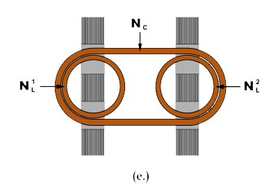
Arrangement F: Dual Ring Cores With Common Control
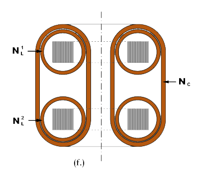
This saturable reactor element configuration features two toroidal cores, each with an AC winding. These two toroidal sub-assemblies are then stacked together and one DC control winding is wound around them both. An important characteristic is that the AC sub-assemblies are balanced so as not to induce an AC voltage into the DC winding.
Conclusion: Circuit Context is Critical
Each saturable reactor element winding configuration has distinct advantages and disadvantages. There is no one best practice for every application. Osborne recommends that you work with saturable reactor design engineers to match the winding configuration to the context of your circuit.
Let’s talk about your project.